
Designing for 3D Printing: SLA, SLS, MJF, FDM, and DMLS
How to choose among SLA, SLS, MJF, FDM, and DMLS, with minimum wall and feature sizes, overhang and orientation rules, drain holes, and achievable tolerances.
Download PDFPick the 3D-printing technology first: SLA for fine detail, SLS or MJF for functional nylon with no supports, FDM for rugged prototypes, DMLS for metal. Keep walls at or above the process minimum (about 1.0 mm / 0.040 in on powder processes), support overhangs shallower than 45 degrees, and add a drain hole to every enclosed cavity.
3D printing builds a part layer by layer, so the design rules are unlike any subtractive or molded process: there is no tool to reach a feature and no cavity to fill, but every layer has to be supported by the one beneath it, and each technology has its own smallest feature it can resolve. Choosing the right process is half the design decision.
This guide covers the rules that matter across the five technologies we run, with the numbers we use. Each is the same check the MASA FabWorks DFM engine applies to your model before you quote, grounded in the ISO/ASTM 52900 and 52911 additive standards and published machine data. Where a rule depends on the technology, we say so.
The five technologies
| Technology | Material class | Resolution | Typical use |
|---|---|---|---|
| SLA / MSLA (resin) | Photopolymer resin | Finest detail, smooth surface | Concept models, fit checks, masters |
| SLS (nylon powder) | PA11, PA12, filled nylons | Isotropic, no supports | Functional plastic parts, living hinges |
| MJF (nylon powder) | PA12, PA11 | Fine, consistent | Functional parts, small runs |
| FDM (filament) | ABS, PC, nylon, PLA, PETG | Coarsest, layer lines visible | Jigs, rugged prototypes, large parts |
| DMLS / SLM (metal) | 316L, AlSi10Mg, titanium, tool steel | Fine, needs support and machining | Metal prototypes, complex metal parts |
Minimum wall and feature size
A wall thinner than the process can resolve prints incompletely or warps off the plate. Powder processes need a thicker minimum than resin because loose powder has to support the melt.
| Technology | Min wall (recommended) | Min positive feature |
|---|---|---|
| SLA | 0.8 mm (0.031 in) | 0.3 to 0.5 mm (0.012 to 0.020 in) |
| SLS | 1.0 to 1.2 mm (0.040 to 0.047 in) | 0.8 to 1.0 mm (0.031 to 0.040 in) |
| MJF | 0.8 to 1.0 mm (0.031 to 0.040 in) | 0.5 to 0.8 mm (0.020 to 0.031 in) |
| FDM | 1.0 to 1.2 mm (0.040 to 0.047 in) | 0.8 to 1.0 mm (0.031 to 0.040 in) |
| DMLS metal | 0.5 mm (0.020 in) | 0.3 to 0.5 mm (0.012 to 0.020 in) |
Overhangs, supports, and orientation
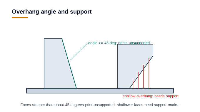
On resin, metal, and filament processes, any surface shallower than about 45 degrees from horizontal needs support structures, which leave witness marks where they attach and cost time to remove. SLS and MJF are self-supporting because the surrounding powder holds the part, so they carry no support marks at all.
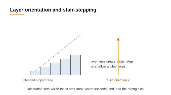
Orientation decides which faces stair-step, where supports land, and which axis is strongest, since a printed part is weakest across the layer lines. Tell us the critical face or the load direction and we orient to suit.
On FDM, a horizontal gap can bridge only a limited span, about 5 to 10 mm (0.2 to 0.4 in), before it sags; longer spans need support or a redesign. Metal printing bridges only about 2 mm (0.08 in) unsupported.
Holes, hollows, and trapped material
Printed holes shrink slightly and are best reamed if they must be precise. As a screening minimum, keep holes at or above 0.5 to 1 mm (0.020 to 0.040 in) on resin, MJF, and metal, and 1.5 to 2 mm (0.060 to 0.080 in) on SLS.
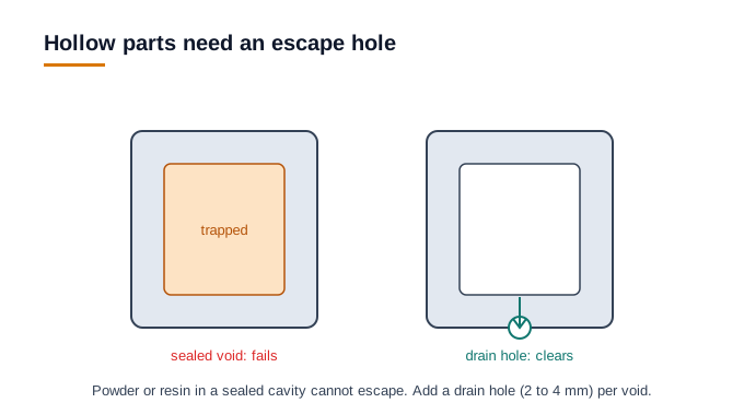
Hollowing a part saves material and time, but a fully enclosed cavity traps liquid resin or loose powder that can never come out. Add at least one drain or escape hole, about 2 to 4 mm (0.08 to 0.16 in), to every enclosed void.
Accuracy and finish
| Technology | Typical tolerance |
|---|---|
| SLA | +/- 0.1 to 0.15 mm (0.004 to 0.006 in) |
| SLS / MJF | +/- 0.3 mm (0.012 in) |
| FDM | +/- 0.3 to 0.4 mm (0.012 to 0.016 in) |
| DMLS metal | +/- 0.1 to 0.2 mm (0.004 to 0.008 in), machined where tighter |
Additive tolerances are looser than machining and scale with part size, so call out only the critical dimensions and plan to machine metal features that need a tight fit. Finishes range from as-printed through bead blast, dye, sanding, and paint; metal parts are typically bead blasted or machined on functional faces.
The DFM checklist
Before you send a model to quote, confirm:
- Technology chosen for the material, detail, and strength the part needs.
- Walls and features at or above the process minimum.
- Overhangs above 45 degrees, or supports accepted on resin, metal, and filament.
- The part oriented for the critical face and load direction (tell us which).
- Enclosed cavities given a drain or escape hole.
- Tight tolerances called out only where needed, metal fits planned for machining.
How MASA FabWorks checks this for you
When you upload a model, our DFM engine measures wall thickness, feature size, overhangs, hole sizes, and enclosed voids against the technology and material you choose, before you quote. It flags a wall too thin to build, an unsupported overhang, or a sealed cavity that will trap powder, and explains the fix. Each result is grounded in the additive design standards behind it. The outcome is a part that builds cleanly and comes off the machine right.
Frequently asked questions
- Which 3D printing process should I choose: SLA, SLS, MJF, FDM, or DMLS?
- SLA resin gives the finest detail and smoothest surface for concept and fit models; SLS and MJF make functional nylon parts with no support marks; FDM is best for rugged jigs and large prototypes; DMLS prints metal. Material, detail, and strength decide it.
- What is the minimum wall thickness for 3D printing?
- About 0.8 mm (0.031 in) on SLA and MJF, 1.0 to 1.2 mm (0.040 to 0.047 in) on SLS and FDM, and 0.5 mm (0.020 in) on DMLS metal. Powder processes need a thicker minimum because loose powder must support the melt.
- Why does a hollow printed part need a drain hole?
- A fully enclosed cavity traps liquid resin or loose powder that can never be removed. Add at least one escape hole of about 2 to 4 mm (0.08 to 0.16 in) to every sealed void.
Related guides
Ready to check your own design? Upload your files. We measure your model against per-process, per-material rules and send a DFM review before you commit to a quote.