
Designing for CNC Machining: A DFM Guide
The design rules that matter most for CNC milling and turning, with the numbers we use and why: walls, radii, pockets, holes, tolerances, and finish.
Download PDFDesign a CNC part around the tools that cut it. Keep walls at or above 1.0 mm (0.040 in) in aluminum and 1.5 mm (0.060 in) in steel, give every internal corner a radius of at least the end-mill radius, hold pocket depth within about 4 times its width on 3-axis, and reserve tight tolerances for the few features that mate or seal.
Most of the cost, lead time, and risk in a machined part is decided before the first chip is cut. The geometry you draw sets which tools can reach it, how many setups it takes, and how tightly it can be held. This guide covers the design rules that matter most for CNC milling and turning, with the actual numbers we use, so you can design a part that quotes faster and machines cleanly the first time.
Every threshold below is the same one the MASA FabWorks DFM engine checks automatically on your uploaded model. Each is derived from published tool geometry and material data, ISO 2768 for general tolerances, ISO 286 for fits, ASME B94.11M and B94.19 for drill and end-mill sizes, and standard machining references, not from guesswork. Where a rule depends on material, we say so.
Wall thickness
Thin walls chatter and deflect under cutting load, which drives tool marks, out-of-tolerance features, and scrapped parts. The stiffer the material, the thinner you can go.
| Feature | Recommended | Achievable | Why |
|---|---|---|---|
| Wall thickness, aluminum | 1.0 mm (0.040 in) | 0.5 mm (0.020 in) | Deflection under cutting force |
| Wall thickness, steel and stainless | 1.5 mm (0.060 in) | 0.8 mm (0.031 in) | Higher cutting forces |
Below the recommended value, expect a cost uplift for lighter cuts and extra fixturing. Below the achievable limit, the feature usually needs a design change.
Internal corners and radii
An internal corner cannot be sharper than the tool that cuts it. Every internal corner carries a radius equal to at least the end-mill radius, so design them in rather than calling out a sharp corner that cannot be made.
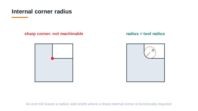
- Recommended internal radius: 1.0 mm (0.040 in) or larger.
- Achievable: 0.5 mm (0.020 in), using a smaller tool at slower feed and higher cost.
Rule of thumb: make internal radii at least one third of the cavity depth so a rigid, larger-diameter tool can reach the corner. If a mating part needs a sharp internal corner, add a corner relief (a small dogbone or T-bone) rather than specifying a zero radius.
Pockets and cavity depth
Deep, narrow pockets force long, slender tools that deflect and chatter. The safe depth depends on how many axes are available.
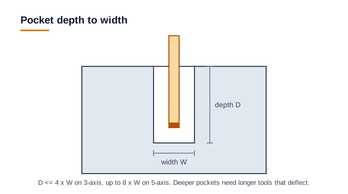
Five-axis access lets the tool tilt in, so shorter, stiffer tools reach the same depth. On 3-axis, keep pocket depth to about 4 times the width; on 5-axis, up to about 8 times. If a pocket runs deeper, expect a slower cut and a wider corner radius.
Holes and bores
Standard drills come in defined sizes, and drilled depth is limited by chip evacuation and drift.
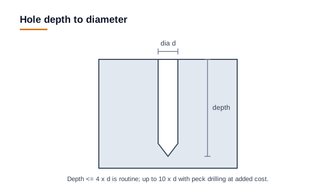
- Minimum hole diameter: 1.0 mm (0.040 in) recommended, 0.5 mm (0.020 in) achievable.
- Drilled depth: up to 4x diameter is routine, up to 10x diameter is possible with peck drilling at added cost.
- For holes with a tolerance tighter than a drilled hole holds, plan for a reamed or bored operation and call out the size and fit class (ISO 286).
Use standard diameters wherever the design allows. A hole sized to an off-list diameter forces a custom tool or an interpolated bore, both slower than a stock drill.
Turned parts: length-to-diameter
Slender turned parts vibrate away from the tool, leaving chatter and taper.
- Length-to-diameter up to 4:1 turns cleanly unsupported.
- Up to 8:1 is achievable with a steady rest or tailstock support, at added setup cost.
- Minimum groove width 0.5 mm (0.020 in); minimum external nose radius 0.4 mm (0.016 in).
Tolerances and cost
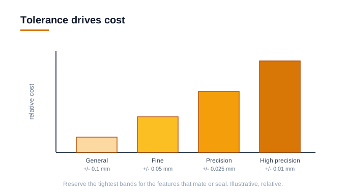
Tolerance is the single biggest cost lever in a machined part. Call out tight tolerances only on the features that need them, and leave the rest at a general standard.
| Tolerance level | Metric | Inch | Typical method |
|---|---|---|---|
| General (ISO 2768 medium) | +/- 0.1 mm | +/- 0.004 in | Standard milling and turning |
| Fine (ISO 2768 fine) | +/- 0.05 mm | +/- 0.002 in | Standard CNC, controlled setup |
| Precision | +/- 0.025 mm | +/- 0.001 in | Tight CNC with in-process gauging |
| High precision | +/- 0.010 mm | +/- 0.0004 in | Grinding, wire EDM, CMM verification |
A part toleranced entirely to high precision can cost several times the same part at a general tolerance with a few critical features called out. Reserve the tightest bands for bearing seats, sealing faces, and mating fits.
Surface finish
The default machined finish is often all a part needs. Specify a finer finish only where function or appearance requires it.
| Finish | Result | Use |
|---|---|---|
| As-machined | Ra 1.6 to 3.2 um | Standard, visible tool marks |
| Bead blast | Uniform matte, tool marks removed | Cosmetic, pre-anodize |
| Anodize Type II | Adds a 12 to 25 um oxide layer | Corrosion resistance, color |
| Hard anodize Type III | 25 to 50 um layer | Wear surfaces, high surface hardness |
The DFM checklist
Before you send a model to quote, confirm:
- Walls at or above the recommended thickness for the material.
- Internal corners carry a radius, reliefs added where a sharp corner is functionally required.
- Pocket and cavity depths within the axis-appropriate ratio.
- Holes at standard diameters, depth within 4x to 10x diameter, tight bores flagged for reaming or boring.
- Turned features within an 8:1 length-to-diameter with support noted beyond 4:1.
- Tight tolerances applied only to critical features, general tolerance elsewhere.
- Surface finish specified only where function or appearance needs it.
How MASA FabWorks checks this for you
When you upload a model, our DFM engine measures the geometry and runs these checks automatically, per process and per material, before you receive a quote. It flags a thin wall, an unreachable pocket, a hole that cannot be drilled at the called-out depth, or a tolerance the process cannot hold, and it explains why and what to change. Each result is grounded in the published standard behind it, so the guidance is traceable, not opinion. The result is a part that is designed to be made, so quoting is faster and the first article comes back right.
Frequently asked questions
- What is the minimum wall thickness for CNC machining?
- Design to about 1.0 mm (0.040 in) in aluminum and 1.5 mm (0.060 in) in steel and stainless. Thinner walls chatter and deflect under cutting load. Roughly 0.5 mm (0.020 in) in aluminum is achievable but adds cost for lighter cuts and extra fixturing.
- How tight a tolerance can CNC machining hold?
- A general band of +/- 0.1 mm (0.004 in) is standard, +/- 0.05 mm (0.002 in) is routine with a controlled setup, and +/- 0.025 mm (0.001 in) is reachable with in-process gauging. A part toleranced tightly throughout can cost several times the same part with only critical features called out, so reserve tight bands for bearing seats, sealing faces, and mating fits.
- Why does an internal corner need a radius?
- An internal corner cannot be cut sharper than the tool that makes it, so it always carries a radius of at least the end-mill radius. Design in a radius of 1.0 mm (0.040 in) or larger, or add a corner relief where a mating part genuinely needs a sharp corner.
Related guides
Ready to check your own design? Upload your files. We measure your model against per-process, per-material rules and send a DFM review before you commit to a quote.