
Designing for Sheet Metal Fabrication: A DFM Guide
Bend radius, flange length, hole placement, K-factor, cut methods, and tolerances for sheet metal parts, with the numbers we use, keyed to material thickness.
Download PDFSheet metal design scales with material thickness, T. Match the inside bend radius to the metal (about 1.0 x T for mild steel and soft aluminum, 3 x T for 6061-T6), keep flanges at 4 x T or longer, hold holes 2.5 x T plus the bend radius from a bend and 2 x T from an edge, and expect about +/- 0.13 mm (0.005 in) on cut features and +/- 0.25 mm (0.010 in) on a single bend.
Sheet metal turns a flat blank into a finished part by cutting and bending, so the design rules are about what a flat pattern can become. Almost everything that drives cost, a bend that cracks, a hole that tears out, a flange too short to form, is set by how features relate to the material thickness. Design to thickness and the part cuts, bends, and holds tolerance the first time.
This guide covers the rules that most affect a sheet metal part, with the numbers we use. Each is the same check the MASA FabWorks DFM engine runs on your model before you quote, grounded in Machinery's Handbook, ISO 2768 for general tolerances, the ANSI B94.11M drill series, and standard press-brake practice. Most sheet rules scale with material thickness, written below as T.
Bend radius
A bend cannot be sharper than the material allows. Too tight an inside radius cracks the outer fiber; too generous wastes flange. Match the inside radius to the material.
| Material | Recommended inside radius | Minimum |
|---|---|---|
| Soft aluminum (3003, 5052) | 1.0 x T | 0.5 x T |
| 6061-T6 aluminum | 3.0 x T | 2.0 x T |
| Mild steel (CRS) | 1.0 x T | 0.5 x T |
| Stainless 304 | 1.5 x T | 1.0 x T |
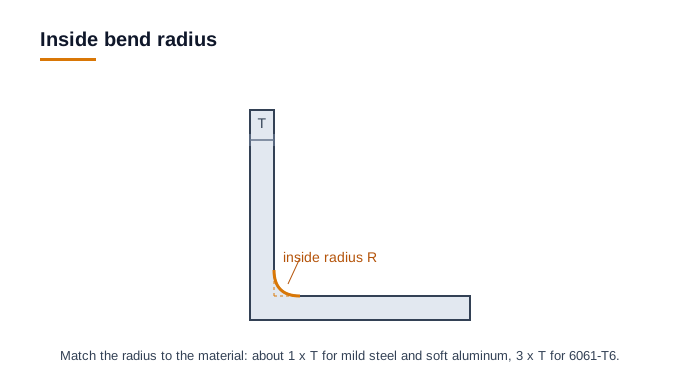
These are starting points for thin sheet. The ratio grows with thickness, and bending with the rolling grain needs more radius than bending across it, so the minimums apply to thin gauge bent across the grain. 6061-T6 is the outlier: in the fully hardened temper it cracks on tight bends, and on plate over about 3 mm (0.12 in) it can need 4 to 6 x T. If a part needs tight bends, specify 5052, or form 6061 in a softer temper and heat-treat it afterward.
Stainless and hardened tempers work-harden as they bend, so they need a larger radius and spring back more. Keep every bend on a part to the same radius where you can, so one tool forms them all.
Flange length and hole placement
A flange shorter than about 4 x T cannot be held in the press brake die through the whole bend, so it forms out of shape. Keep flanges at 4 x T or longer.
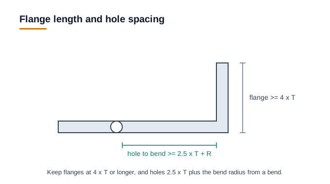
Holes and slots placed too close to a bend distort as the metal draws in. Keep a hole at least 2.5 x T plus the inside bend radius from the start of a bend. Keep the hole's edge at least 2 x T from an outside edge so it does not bulge or tear out (1.5 x T is the floor, and stainless wants about 3 x T).
K-factor and the flat pattern
When metal bends, the inner face compresses and the outer face stretches, so the length that stays neutral, the neutral axis, shifts toward the inside of the bend. The K-factor is where that axis sits as a fraction of thickness, and it sets the flat blank length.
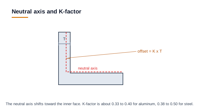
K-factor runs about 0.33 to 0.40 for aluminum and 0.38 to 0.50 for steel. You do not need to supply it; we apply the right bend allowance for the material and tooling. What matters for your design is that a bend consumes material, so dimension to the finished part, not to the flat blank.
Holes, cutting, and tolerance
We cut blanks by laser, punch, or waterjet, and the smallest reliable hole depends on which.
| Cut method | Smallest hole | Note |
|---|---|---|
| Fiber laser | about 0.5 x T (down to ~0.8 mm / 0.031 in) | no tool wear, clean edge |
| Punch | at least T (about 1.0 mm / 0.040 in and up) | die needs a diameter at least the thickness |
| Waterjet | about 1.8 mm (0.070 in) for most materials | no heat-affected zone, wider kerf |
Laser-cut features hold about +/- 0.13 mm (0.005 in) to each other on thin sheet, and +/- 0.1 mm (0.004 in) is achievable on a precision laser for individual features, called out only where needed. Bending adds variation: plan on about +/- 0.25 mm (0.010 in) for a single bend on thin sheet, widening across several bends and on thicker stock. Stainless holds a slightly looser band because it springs back more.
Fasteners and finishing
Thin sheet has too little thread engagement to tap reliably (where that line falls depends on the thread size), so cycled fasteners use clinch (self-clinching) inserts pressed into the sheet, sized to the hole per the insert standard. For finish, aluminum anodizes or powder-coats; carbon steel takes zinc plating or powder coat, not anodize; stainless is usually passivated rather than plated. Choose the finish with the substrate in mind, since not every finish pairs with every metal.
The DFM checklist
Before you send a model to quote, confirm:
- Inside bend radius matched to the material, ideally one radius across the part.
- Flanges at 4 x T or longer.
- Holes 2.5 x T plus the bend radius from any bend, and 2 x T from an edge.
- The smallest holes within reach of the intended cut method.
- Tight tolerances called out only on features that need them.
- Threaded features planned as clinch inserts on thin sheet, finish matched to the metal.
How MASA FabWorks checks this for you
When you upload a model, our DFM engine unfolds it, measures each bend radius, flange, hole, and edge distance against the material and thickness, and checks the finish and any threaded features for compatibility, before you receive a quote. It flags a bend that will crack, a flange too short to form, or a hole that will tear out, and explains the fix. Each result is grounded in the published standard behind it, so the guidance is traceable. The result is a flat pattern that bends cleanly and a part that comes back to size.
Frequently asked questions
- What is the minimum bend radius for sheet metal?
- Match it to the material: about 1.0 x T for soft aluminum and mild steel, 1.5 x T for 304 stainless, and 3 x T for 6061-T6, where T is the material thickness. Too tight an inside radius cracks the outer fiber; 6061-T6 cracks most readily, and stainless springs back more.
- How close can a hole be to a bend or an edge?
- Keep a hole at least 2.5 x T plus the inside bend radius from the start of a bend so it does not distort as the metal draws in, and its edge at least 2 x T from an outside edge (about 3 x T for stainless) so it does not tear out.
- Do I need to supply the K-factor?
- No. The K-factor (about 0.33 to 0.40 for aluminum, 0.38 to 0.50 for steel) sets the flat-blank length, and we apply the right bend allowance for the material and tooling. Dimension your drawing to the finished part, not the flat blank.
Related guides
Ready to check your own design? Upload your files. We measure your model against per-process, per-material rules and send a DFM review before you commit to a quote.