
Designing for Injection Molding: A DFM Guide
Wall thickness, draft, ribs and bosses, undercuts, gates, and tolerances for injection-molded parts, keyed to resin, with the numbers we use.
Download PDFInjection molding rewards a uniform, resin-appropriate wall. Hold a nominal wall (about 1.2 mm / 0.047 in for ABS), keep thick-to-thin transitions under 3 to 1, add draft to every ejection face, keep ribs at or below 60 percent of the wall, and design undercuts out so the tool needs no side action.
Injection molding rewards discipline at the design stage. A molded part is made hundreds or thousands of times from one tool, so a wall that sinks, a rib that warps, or an undercut that forces a side action is a defect or a cost that repeats on every shot. Get the geometry right and the tool is simpler, the cycle is faster, and the parts are consistent.
This guide covers the design rules that most affect moldability, with the numbers we use. Each is the same check the MASA FabWorks DFM engine runs on your model before you quote, and each is grounded in published polymer and tooling references. Molding rules depend heavily on the resin, so the values below are keyed to material where it matters.
Wall thickness
Wall thickness sets fill, cooling, and cycle time. Too thin and the cavity will not fill (short shot). Too thick and the part sinks, warps, and traps voids as the core cools slower than the skin. Design to a resin-appropriate nominal wall and hold it as uniform as possible.
| Resin | Typical wall range | Practical minimum |
|---|---|---|
| ABS | 1.2 to 3.5 mm (0.047 to 0.138 in) | 1.2 mm (0.047 in) |
| Polycarbonate (PC) | 1.0 to 4.0 mm (0.039 to 0.157 in) | 1.0 mm (0.040 in) |
| Polypropylene (PP) | 0.8 to 3.8 mm (0.031 to 0.150 in) | 0.8 mm (0.031 in) |
| Nylon (PA6, PA66) | 0.8 to 2.9 mm (0.031 to 0.114 in) | 0.8 mm (0.031 in) |
| POM (acetal) | 0.8 to 3.0 mm (0.031 to 0.118 in) | 0.8 mm (0.031 in) |
| PEEK | 1.0 to 3.0 mm (0.039 to 0.118 in) | 1.0 mm (0.040 in) |
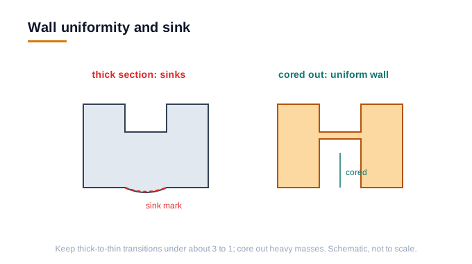
Keep wall transitions gradual. A thick-to-thin ratio beyond about 3 to 1 causes differential cooling, which shows up as sink and warp. Where a thick section is unavoidable, core it out rather than leaving a solid mass.
Draft angle
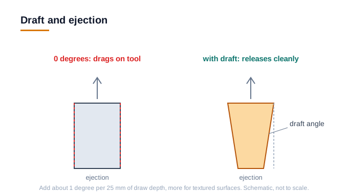
Every face parallel to the direction the part is ejected needs draft, or the part drags on the tool and scuffs, sticks, or ejector-pins through. The rougher the texture, the more draft it needs.
| Surface | Recommended draft |
|---|---|
| Smooth, polished (SPI A) | 0.5 to 1 degree |
| Semi-gloss (SPI B) | 1 to 2 degrees |
| Matte (SPI C) | 1.5 to 3 degrees |
| Light texture | 3 to 5 degrees |
| Heavy texture | 5 to 7 degrees |
Rule of thumb: add roughly 1 degree of draft for every 25 mm (1 in) of draw depth, and add draft for textured surfaces on top of that. Draft is nearly free at the design stage and expensive to add after the tool is cut.
Ribs and bosses
Ribs add stiffness without thickening the wall, but a rib that is too thick pulls a sink mark on the opposite face.
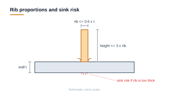
- Rib thickness: keep at or below 60 percent of the nominal wall (for stiffer resins such as PP and PA6, closer to 50 percent).
- Rib height: up to about 3 times the rib thickness.
- Boss outer wall: keep at or above 40 percent of the boss outside diameter, and connect bosses to a wall or rib rather than leaving them standing alone.
Corners, sink, and stress
- Add a radius to every internal corner. Sharp internal corners concentrate stress and cause cracking; a radius of about half the wall thickness is a good default.
- Avoid sharp external corners; a small radius (0.5 mm / 0.020 in and up) improves flow and durability.
- Watch for sink opposite thick features. A local section thicker than about 4 mm (0.16 in) in ABS (higher in some resins) risks a visible sink mark.
Undercuts
Any undercut prevents the part from pulling straight off the core, so it forces a side action (a slider or lifter) in the tool, which adds cost and cycle time.
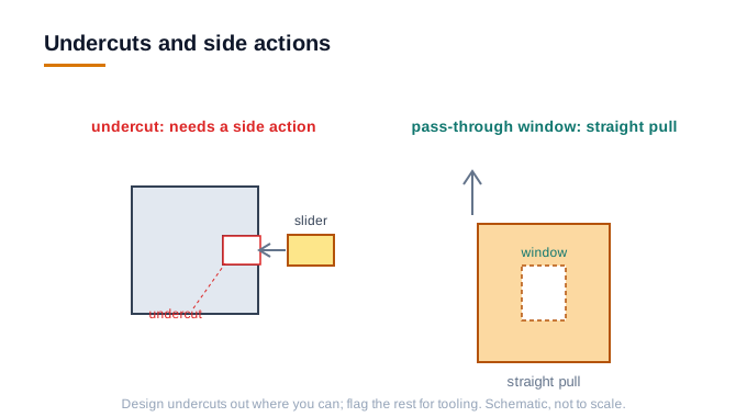
Design undercuts out where you can, for example by adding a pass-through window under a snap hook so the tool can form it on a straight pull. Where an undercut is functional, flag it early so the tool is quoted correctly.
Gates, weld lines, and fill
- Fill path: a single gate can reliably fill roughly 100 mm (4 in) of flow length on a cold runner, more on a hot runner. Long, thin, or complex parts may need multiple gates.
- Weld lines: where two flow fronts meet (around a hole or boss) the part is weaker and may show a witness line. Position holes and gates so weld lines fall away from load-bearing or cosmetic areas.
- Gate location is a cosmetic and structural decision; tell us the show surface and the load path and we will place the gate to suit.
Tolerances
Molded tolerances are driven by shrinkage, which varies by resin, so they are looser than machined tolerances and resin-dependent. Call out tight tolerances only where a part mates or seals.
| Resin | Achievable on a small feature |
|---|---|
| ABS | +/- 0.05 to 0.1 mm (0.002 to 0.004 in) |
| PP | +/- 0.075 to 0.15 mm (0.003 to 0.006 in) |
| Nylon (PA6) | +/- 0.1 to 0.2 mm (0.004 to 0.008 in) |
Glass-filled grades shrink less but warp anisotropically, so treat their tolerances as grade-specific rather than assuming they are simply tighter.
The DFM checklist
Before you send a model to quote, confirm:
- Nominal wall within the resin range, held uniform, thick-to-thin transitions kept under 3 to 1.
- Draft on every ejection face, matched to the surface finish and draw depth.
- Ribs at or below 60 percent of wall, bosses connected and correctly proportioned.
- Internal corners radiused; thick masses cored out to prevent sink.
- Undercuts removed where possible, remaining ones flagged for side actions.
- Flow length within single-gate reach or multi-gating planned; weld lines steered away from critical areas.
- Tight tolerances only on mating and sealing features.
How MASA FabWorks checks this for you
When you upload a model, our DFM engine measures wall thickness and uniformity, checks draft against the intended finish, evaluates rib and boss proportions, detects undercuts and sink risk, and estimates fill and weld-line behavior, per resin, before you receive a quote. It tells you where a wall will sink, where a face lacks draft, or where an undercut will drive tooling cost, and why. Each result is grounded in the published reference behind it, so the guidance is traceable. The outcome is a part designed to mold cleanly, so tooling quotes faster and first-article parts come back consistent.
Frequently asked questions
- What wall thickness should an injection-molded part use?
- Use a uniform, resin-appropriate nominal wall: about 1.2 to 3.5 mm (0.047 to 0.138 in) for ABS, and 0.8 mm (0.031 in) and up for PP and nylon. Hold it uniform and keep any thick-to-thin transition under about 3 to 1, since uneven walls sink and warp.
- How much draft does an injection-molded part need?
- Plan on roughly 1 degree of draft for every 25 mm (1 in) of draw depth, with 0.5 to 1 degree on a polished face and 3 to 5 degrees on a textured one. Every face parallel to ejection needs draft or the part drags on the tool.
- How thick should a rib be on a molded part?
- Keep a rib at or below 60 percent of the wall it joins (closer to 50 percent in stiffer resins like PP and nylon), and up to about 3 times its thickness tall. A thicker rib pulls a visible sink mark on the opposite face.
Related guides
Ready to check your own design? Upload your files. We measure your model against per-process, per-material rules and send a DFM review before you commit to a quote.