
GD&T, Tolerances, and Fits: A Primer
General tolerances, the GD&T controls and feature control frame, material condition and bonus tolerance, and how to choose an ISO 286 fit, with achievable bands by process.
Download PDFPut a general ISO 2768 class in the title block and tighten only the features that mate, seal, or locate. GD&T states tolerances as zones tied to datums (form, orientation, location, profile, runout), and ISO 286 names the fits: H7/g6 slides, H7/k6 locates, H7/p6 presses. Match the fit to the function and state it in standard notation.
A tolerance is a promise about how much a dimension can vary and still work. Too loose and parts do not fit or seal; too tight and the price climbs for no functional gain. Geometric dimensioning and tolerancing (GD&T) and the ISO fit system are the shared language for stating those promises precisely, so a part means the same thing to the designer, the machinist, and the inspector. This primer covers the essentials: general tolerances, the GD&T controls, and how to pick a fit.
The standards behind this are public: ISO 2768 for general tolerances, ISO 286 for limits and fits, and ASME Y14.5 and ISO 1101 for GD&T symbols. Every achievable band we quote below is the same one the MASA FabWorks DFM engine screens against per process.
General tolerances first
Most dimensions on a part do not need an individual tolerance. ISO 2768 assigns a default band by the size of the feature and a chosen class, so the drawing stays clean and only the critical dimensions carry a called-out tolerance.
| ISO 2768 class | Character | Typical band on a small feature |
|---|---|---|
| Fine (f) | Precision | +/- 0.05 mm (0.002 in) |
| Medium (m) | General | +/- 0.1 mm (0.004 in) |
| Coarse (c) | Rough | +/- 0.2 to 0.3 mm (0.008 to 0.012 in) |
| Very coarse (v) | As-cut | +/- 0.5 mm (0.020 in) and up |
Put a general class in the title block, then tighten only the features that mate, seal, or locate.
Achievable tolerance by process
Tolerance is not free, and what is achievable depends on the process. Asking a molded or cast feature to hold a machined tolerance forces a secondary machining operation.
| Process | Typical achievable (small feature) |
|---|---|
| CNC machining | +/- 0.025 to 0.05 mm (0.001 to 0.002 in), tighter with grinding |
| Sheet metal | +/- 0.2 mm (0.008 in) |
| Die casting | +/- 0.1 to 0.2 mm (0.004 to 0.008 in) as-cast |
| Injection molding | resin-dependent, roughly +/- 0.05 to 0.2 mm (0.002 to 0.008 in) |
| 3D printing | +/- 0.1 to 0.3 mm (0.004 to 0.012 in) by technology |
The GD&T controls
GD&T states tolerances as zones tied to datums, which controls form and relationship, not just size. The controls fall into groups:
- Form: flatness, straightness, circularity, cylindricity. No datum needed; controls a surface against itself.
- Orientation: perpendicularity, parallelism, angularity. Controls a feature relative to a datum.
- Location: position, concentricity, symmetry. Position is the workhorse: it holds a feature within a zone about its true location.
- Profile: profile of a line or surface. Controls a whole contour within a tolerance band.
- Runout: circular and total runout. Controls a rotating surface relative to an axis.
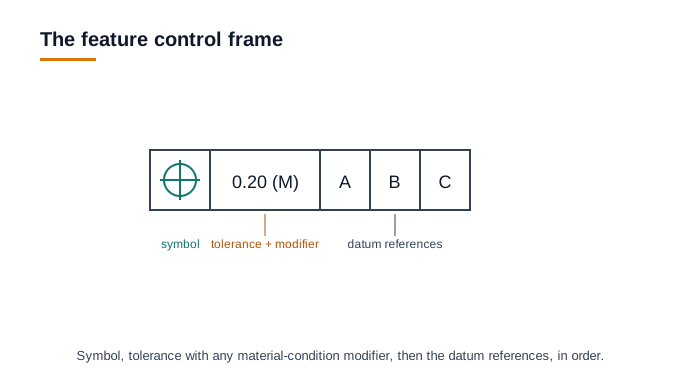
Each control is written in a feature control frame: the symbol, the tolerance zone with any modifier, and the datums it is measured from, in order. Datums are the reference faces or axes, labelled A, B, C, that fix how the part is held for measurement, so a stated datum scheme is what makes a tolerance repeatable.
Material condition and bonus tolerance
Position tolerances often carry a material-condition modifier. At maximum material condition (MMC), a feature at its worst-case material size (a hole at its smallest, a pin at its largest) gets the stated tolerance, and any departure from that size adds bonus tolerance. This matches how parts actually assemble and can widen the usable tolerance without loosening the fit, so it lowers cost where it applies.
Fits: clearance, transition, interference
When a shaft goes in a hole, the fit is the intended looseness or tightness. ISO 286 defines it with a tolerance grade (the IT number, smaller is tighter) and a letter that positions the band, using a hole-basis system where the hole is the constant.
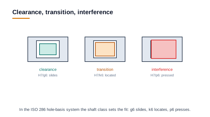
| Fit | Example (hole basis) | Behavior |
|---|---|---|
| Clearance | H7/g6 | Always has a gap, slides and rotates freely |
| Transition | H7/k6 | Small gap or slight grip, locates precisely |
| Interference | H7/p6 | Always tight, pressed or shrunk together, transmits load |
Pick the fit from the function: a rotating shaft wants clearance, a located dowel wants transition, a permanently seated bushing wants interference. State it as the standard callout and the machinist and inspector both know exactly what to hold.
The checklist
- A general ISO 2768 class in the title block.
- Tight tolerances only on mating, sealing, and locating features.
- Tolerances achievable in the chosen process, or secondary machining planned.
- Datums defined for any geometric control.
- Fits called out with the standard hole-basis notation.
How MASA FabWorks checks this for you
Our DFM engine screens each toleranced feature against what the chosen process and material can hold, flags a callout tighter than the process supports, and points to the operation (reaming, grinding, machining a cast face) that would be needed. Each band is grounded in the ISO tolerance standards behind it, so the guidance is traceable and the quote reflects the real cost of the tolerances you asked for.
Frequently asked questions
- What is the difference between clearance, transition, and interference fits?
- A clearance fit (for example H7/g6) always leaves a gap and slides or rotates freely; a transition fit (H7/k6) locates precisely with a slight gap or grip; an interference fit (H7/p6) is always tight and is pressed or shrunk together to transmit load.
- What is GD&T?
- Geometric dimensioning and tolerancing is a standard language (ASME Y14.5, ISO 1101) that states tolerances as zones tied to datums, controlling a feature's form, orientation, location, profile, and runout, not just its size. That makes a tolerance mean the same thing to designer, machinist, and inspector.
- What is bonus tolerance at maximum material condition (MMC)?
- At maximum material condition, a feature at its worst-case material size (a hole at its smallest, a pin at its largest) gets the stated position tolerance, and any departure from that size adds bonus tolerance. It matches how parts actually assemble and can widen the usable tolerance without loosening the fit.
Related guides
Ready to check your own design? Upload your files. We measure your model against per-process, per-material rules and send a DFM review before you commit to a quote.